Voron V0.1 - SKR Pico Wiring
Initial Removal of Jumpers
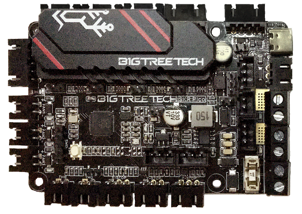
- The BTT SKR Pico will arrive without any jumpers being set.
Initial Preparation - Set Jumpers
- All Jumpers should be removed from the SKR Pico board.
- If you want to open the above picture, in a new tab of your web browser, then click here
Voltage Selection Header and Other Headers
-
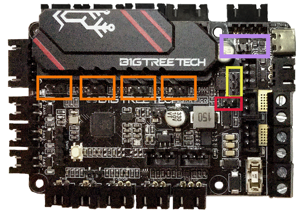
Ensure the removal of the SW_USB 5V power supply jumper (“SW_USB header, shown in the PURPLE box”) which avoids the interaction between the USB 5V of Raspberry Pi and the DC-DC 5V of the motherboard.
-
In the diagram below, ensure all of “DIAG Jumpers” (shown in the ORANGE boxes) are removed to avoid the influence of TMC2209 DIAG on the endstops.
-
Ensure the removal of the SELECT-PROXIMITY-I/O-PIN jumper (shown in the YELLOW box). This SELECT-PROXIMITY-I/O-PIN jumper selects which connector uses IO22 pin (either connector PS or PROBE). Since the Voron printer does not use a proximity sensor (inductive probe), remove the jumper.
-
Ensure the removal of the SELECT-PROXIMITY-STYLE jumper (shown in the RED box). Since the Voron printer does not use a probe device, ensure this header is empty.
IMPORTANT: Double check all the GREEN jumpers are removed, especially the headers called out by the COLORED BOXES, BEFORE the power supply is connected.
- If you want to open the above picture, in a new tab of your web browser, then click here
MCU
-
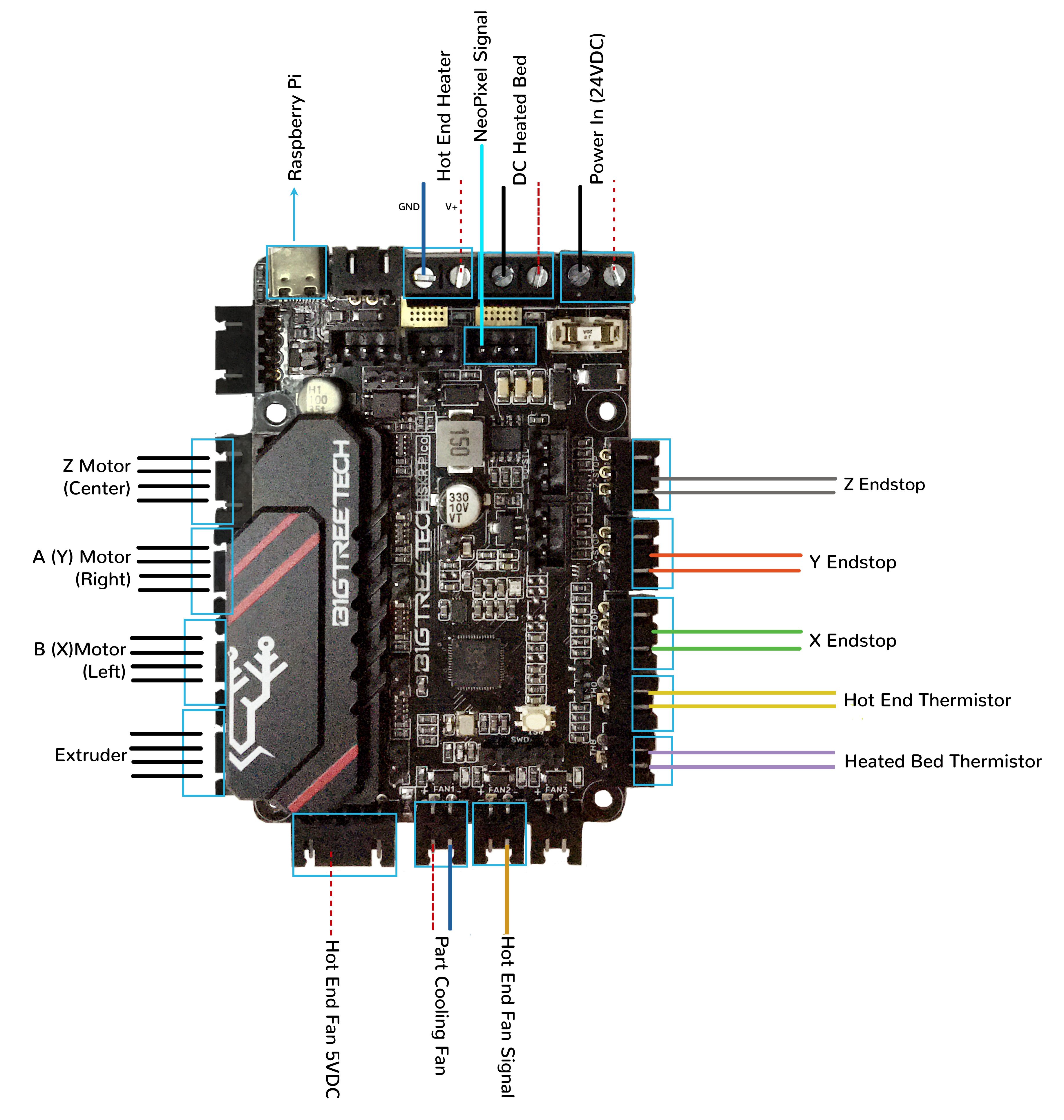
- Plug in stepper motors for X positions X (motor connector)
-
- Plug in stepper motors for Y in positions Y (motor connector)
-
- Plug in stepper motors for Z in positions Z1 (motor connector)
-
- Plug in stepper motors for E in positions E (motor connector)
-
- Plug Hot End thermistor to thermistor TH0 (IO27)
-
- Plug Hot End heater in to HE (IO23)
-
- Plug Hot End Fan Signal in to FAN2 (IO18)
-
- Plug Hot End Fan V+ (+5VDC) in to LASER connector’s 5V PIN
-
- Plug Part Cooling Fan in to FAN1 (IO17)
-
- Plug Bed Thermistor in to THB (IO26)
-
- Connect The DC bed to HB (IO21)
-
- Connect X end stop to X-STOP connector (IO4)
-
- Connect Y end stop to Y-STOP connector (IO3)
-
- Connect Z end stop to Z-STOP connector (IO25)
-
- Wire 24V and -V from DC power supply to Power_In
- if using USB to communicate with Pi:
-
- Connect USB Cable to the SKR Pico board, but do not connect it yet to your Raspberry Pi
-
- if using UART (3-wire serial communication) with Pi:
-
- Move Hot End Fan V+ (+5VDC) in to SERVOS connector’s 5V PIN
-
- Connect UART serial cable (3-wire communication) to the SKR Pico board’s “Raspberry Pi” connector, but do not connect it yet to your Raspberry Pi
MCU Diagram
- If you want to open the above diagram, in a new tab of your web browser, and have the ability to zoom and download the diagram in JPG format then click here
Powering the Raspberry Pi & Setting up UART Serial Communications with the Raspberry Pi
The Klipper Configuration file for SKR Pico board
The Klipper Configuration file from VoronDesign/Voron-0 GitHub Repo, Voron0.1 branch for SKR Pico board is located here
URL Resources Links for the SKR Pico (PIN Diagrams and Repo)
After I have Wired up the MCU Board, What Comes Next?
-
Once the MCU board is wired up and wire management has been performed, the next step is to install Mainsail/Fluidd or Octoprint, please see The Build ═► Software Installation
-
Once Mainsail/Fluidd or Octoprint has been installed, the next step is to compile and install the Klipper Firmware, please use the Color Pin Diagram, look for “Klipper Building Options”; an alternative source of information on how to build and install the Klipper firmware for the SKR Pico is located here or the picture of the menu config screen for Klipper
-
Once the MCU board has the Klipper Firmware Installed, the next step is to create/edit the Klipper Config file (skr-pico-v1.0.cfg rename it to printer.cfg) to ensure your Voron build matches your Klipper Config file, please see the file located here;
-
Please use the Color PIN Diagrams, displayed here, as a source of information.
-
Please consult The Build ═► Software Configuration on how to edit the Klipper Config file.
-
-
After creating/editing the Klipper Config file (skr-pico-v1.0.cfg renamed to printer.cfg), the next step is to check all the motors and the mechanics of the Voron printer, please see The Build ═► Initial Startup Checks


