Voron V0.1 - SKR mini E3 V3.0 Wiring
Initial Removal of Jumpers
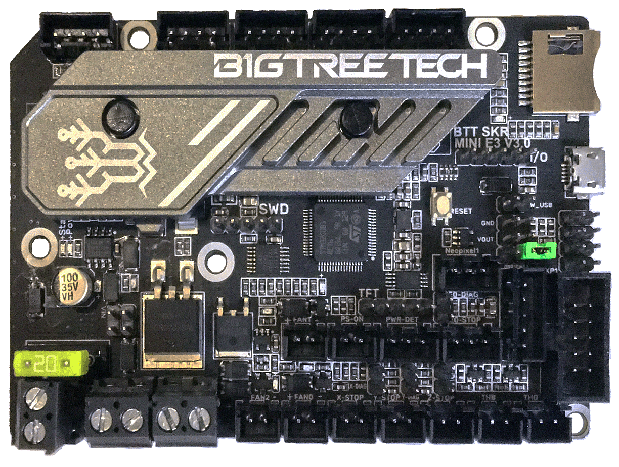
- There is only one jumper on the SKR mini E3 V3.0 board. This jumper is called “Neo-PWR1” jumper. See the next section about this jumper.
Initial Preparation - Set Jumper
- The GREEN Neo-PWR1 jumper setting will decide the source of the SKR’s 5V rail. The board’s 5V rail can be sourced from the board itself or from an external DCDC bridge module. One can purchase an external DCDC bridge module (sold separately) to power 5V NeoPixel LEDs. This bridge module is called the “DCDC Mode V1.0” board. Since the Voron printer does not require the extra DCDC bridge module, set the Neo-PWR1 jumper so that the board’s 5V rail will be powered by the MCU (as shown by the GREEN jumper in the diagram below).
- If you want to open the above picture, in a new tab of your web browser, then click here
USB Voltage Selection Header and Other Headers
-
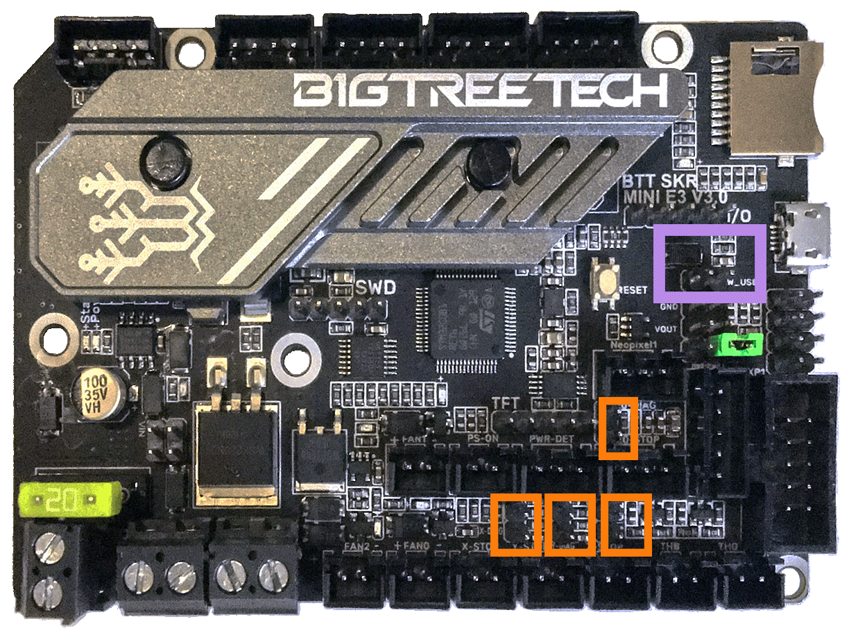
Ensure the removal of the SW_USB 5V power supply jumper (“SW_USB header, shown in the PURPLE box”) which avoids the interaction between the USB 5V of Raspberry Pi and the DC-DC 5V of the motherboard.
-
Ensure all of “DIAG Jumpers” (shown in the ORANGE boxes) are removed to avoid the influence of TMC2209 DIAG on the endstops.
IMPORTANT: Double check the GREEN jumper is set appropriately (and the other jumpers are removed), especially the headers called out by the COLORED BOXES, BEFORE the power supply is connected.
- If you want to open the above picture, in a new tab of your web browser, then click here
MCU
-
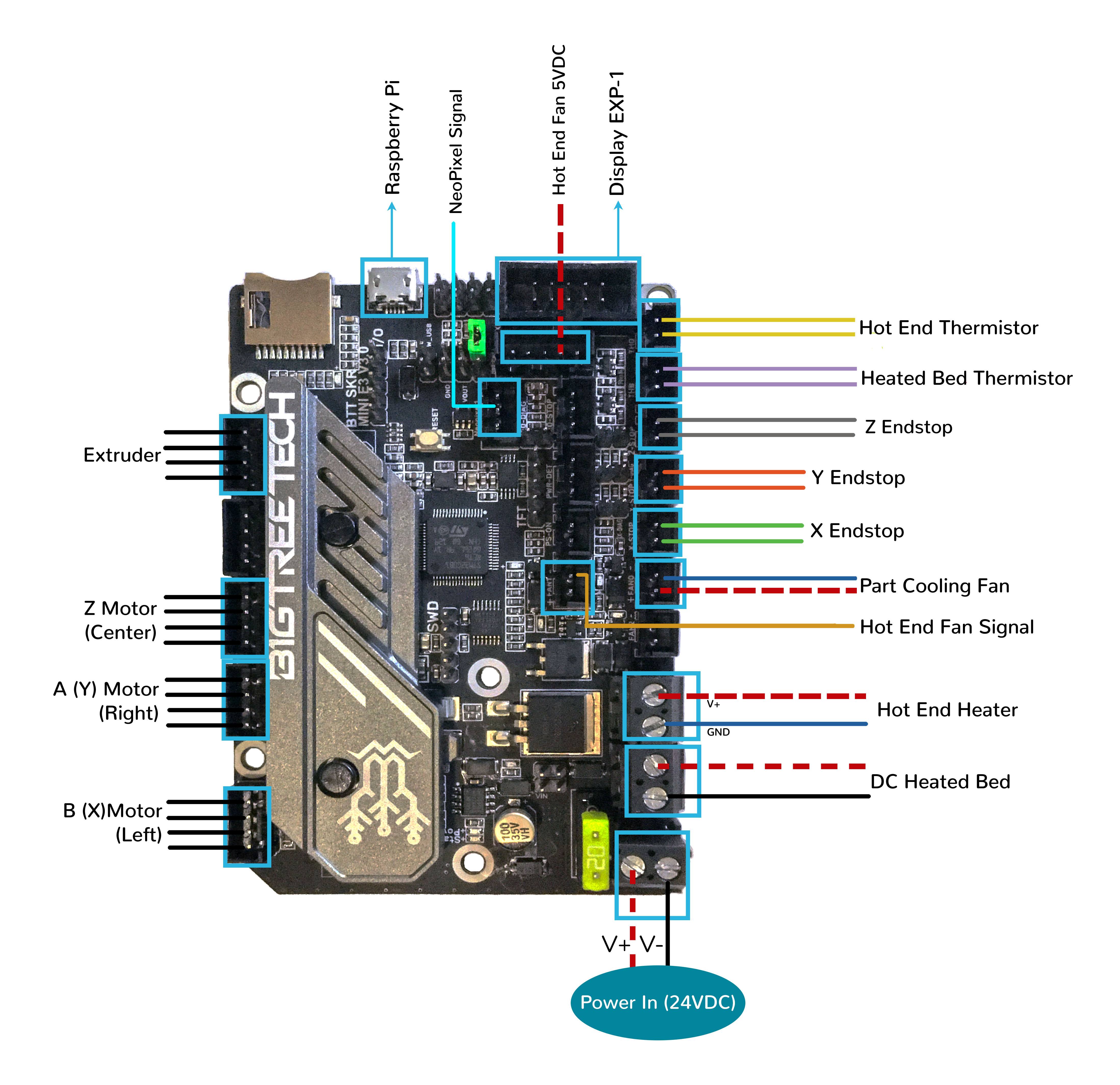
- Plug in stepper motors for X in positions Xm (motor connector)
-
- Plug in stepper motors for Y in positions Ym (motor connector)
-
- Plug in stepper motors for Z in positions ZAm (motor connector)
-
- Plug in stepper motors for E in positions Em (motor connector)
-
- Plug Hot End thermistor to thermistor TH0 (PA0)
-
- Plug Hot End heater in to E0 (PC8)
-
- Plug Hot End Fan Signal in to FAN1 (PC7)
-
- Plug Hot End Fan’s V+ (+5VDC) into Z-Probe’s NPWR PIN
-
- Plug Part Cooling Fan in to FAN0 (PC6)
-
- Plug Bed Thermistor in to THB (PC4)
-
- Connect The DC bed to HB (PC9)
-
- Connect X end stop to X-STOP connector (PC0)
-
- Connect Y end stop to Y-STOP connector (PC1)
-
- Connect Z end stop to Z-STOP connector (PC2)
-
- Wire 24V and -V from DC power supply to VIN and GND terminals of the POWER/DCIN connector
- if using USB to communicate with Pi:
-
- Connect USB Cable to your SKR mini E3, but do not connect it yet to your Raspberry Pi
-
- if using UART (3-wire serial communication) with Pi:
-
- Connect UART serial cable to your SKR mini E3, but do not connect it yet to your Raspberry Pi
MCU Diagram
- If you want to open the above diagram, in a new tab of your web browser, and have the ability to zoom and download the diagram in JPG format then click here
Raspberry Pi
Power
- The BTT SKR mini E3 V3.0 board is NOT capable of providing 5V power to run your Raspberry Pi.
Setting up UART Serial Communications with the Raspberry Pi
The Klipper Configuration file for SKR mini E3 V3.0 Board
The Klipper Configuration file from VoronDesign/Voron-0 GitHub Repo, Voron0.1 branch for SKR mini E3 V3.0 board is located here;
URL Resources Links for the SKR mini E3 V2.0 (PIN Diagrams and Repo)
After I have Wired up the MCU Board, What Comes Next?
-
Once the MCU board is wired up and wire management has been performed, the next step is to install Mainsail/Fluidd or Octoprint, please see The Build ═► Software Installation
-
Once Mainsail/Fluidd or Octoprint has been installed, the next step is to compile and install the Klipper Firmware, please use the Color Pin Diagram displayed here, look for “Klipper Building Options”; an alternative source of information on how to build and install the Klipper firmware for the SKR mini E3 V3.0 is located here
-
Once the MCU board has the Klipper Firmware Installed, the next step is to create/edit the Klipper Config file (skr-mini-E3-v3.0.cfg rename it to printer.cfg) to ensure your Voron build matches your Klipper Config file, please see the file located here; Select “V0 SKR mini e3 3.0”;
-
Please use the Color PIN Diagrams, displayed here, as a source of information;
-
Please consult The Build ═► Software Configuration on how to edit the Klipper Config file.
-
-
After creating/editing the Klipper Config file (skr-mini-E3-v3.0.cfg renamed to printer.cfg), the next step is to check all the Motors and the mechanics of the Voron printer, please see The Build ═► Initial Startup Checks